
FANUC Series 30i/300i/300is-MODEL A. Machining Center System. User's manual — page 207
12.SETTING AND DISPLAYING DATA
OPERATION
B-63944EN/03
- 1612 -
12.3.10
Displaying and Switching the Display Language
The language used for display can be switched to another language.
A display language can be set using a parameter. However, by
modifying the setting of the display language on this screen, the
display language can be switched without turning off then on the
power.
Displaying and setting the display language
Procedure
1
Press function key
.
2
Press the continuous menu key
several times.
3
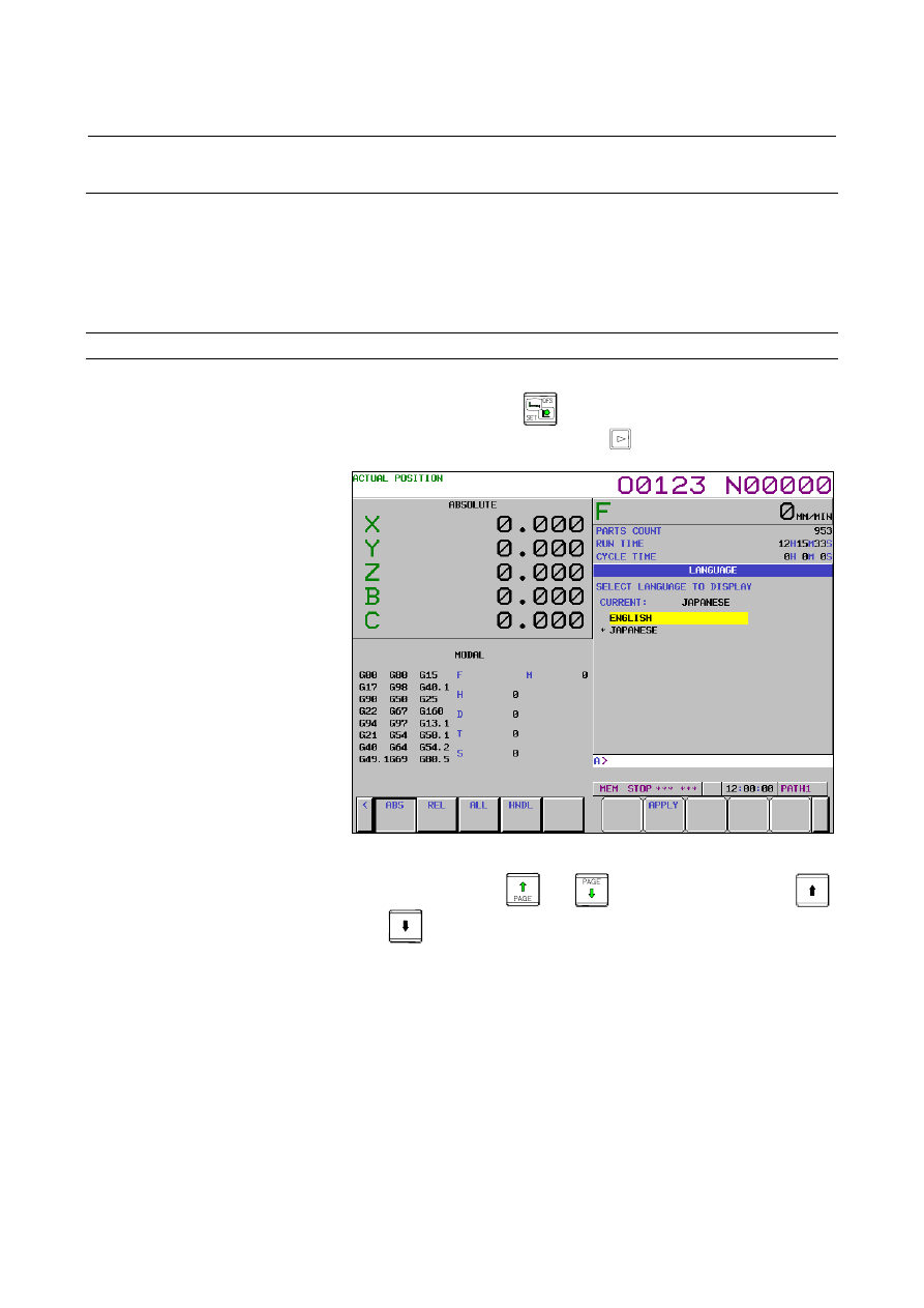
Press soft key [LANGUAGE] to display the language screen.
Fig. 12.3.10 (a) LANGUAGE screen (10.4-inch)
4 Press page key
or
, then press cursor keys
,
to move the cursor to a desired display language.
5 Press operation soft key [APPLY]. The display language is
switched to the selected language. The language specified on this
screen continues to be used if the power is turned off then back
on.
B-63944EN/03
OPERATION
12.SETTING AND DISPLAYING DATA
- 1613 -
Explanation
- Language switching
The language screen can be displayed if bit 0 (NLC) of parameter No.
3280 is set to 0.
- Selectable languages
The display languages selectable on this screen are as follows:
1. English
2. Japanese
3. German
4. French
5. Chinese
(Traditional)
6. Chinese
(Simplified)
7. Italian
8. Korean
9. Spanish
10. Dutch
11. Danish
12. Portuguese
13. Polish
14. Hungarian
15. Swedish
16. Czech
17. Russian
18. Turkish
Among the languages listed above, English and other usable
languages are displayed on the screen as a list of switchable
languages.
Limitation
- Language parameter modification on the parameter screen
Which language to use for display is specified with parameter No.
3281. This parameter can be modified using the parameter screen as
well. However, if a modification is made on the parameter screen, the
new setting is not reflected until “APPLY” operation is performed on
the language screen or the power is turned on again. If an invalid
value is set in parameter No. 3281 on the parameter screen, the screen
is displayed in English after the power is turned on again.
12.SETTING AND DISPLAYING DATA
OPERATION
B-63944EN/03
- 1614 -
12.3.11
Protection of Data at Eight Levels
You can set eight CNC and PMC operation levels and one of eight
protection levels for each type of CNC and PMC data.
When an attempt is made to change CNC and PMC data or output it to
an external unit, the operation level is compared with the protection
level to determine whether to allow the change or external output.
12.3.11.1
Operation level setting
You can set eight CNC and PMC operation levels.
Displaying and setting the operation level setting screen
Procedure
1
Press function key
.
2
Press the continuous menu key
several times until soft key
[PROTECT] is displayed.
3
Press soft key [PROTECT].
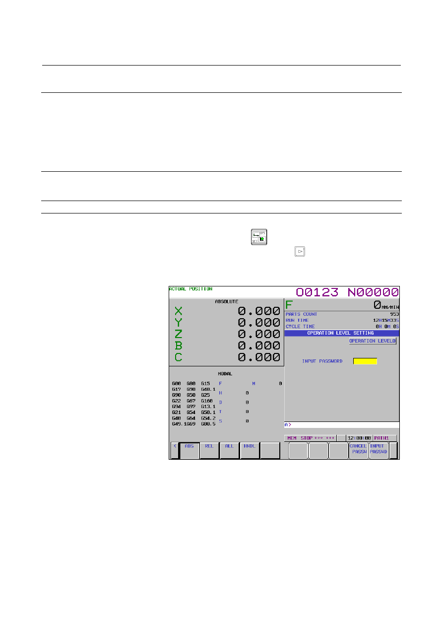
The operation level setting screen shown below is displayed.
Fig. 12.3.11.1 (a) Operation level setting screen (10.4-inch)
4
Key in the password for an operation level to be set/modified,
then press soft key [INPUT PASSWD].
5 To return the operation level to 0, 1, 2, or 3, press soft key
[CANCEL PASSWD].
B-63944EN/03
OPERATION
12.SETTING AND DISPLAYING DATA
- 1615 -
Explanation
- Operation level setting
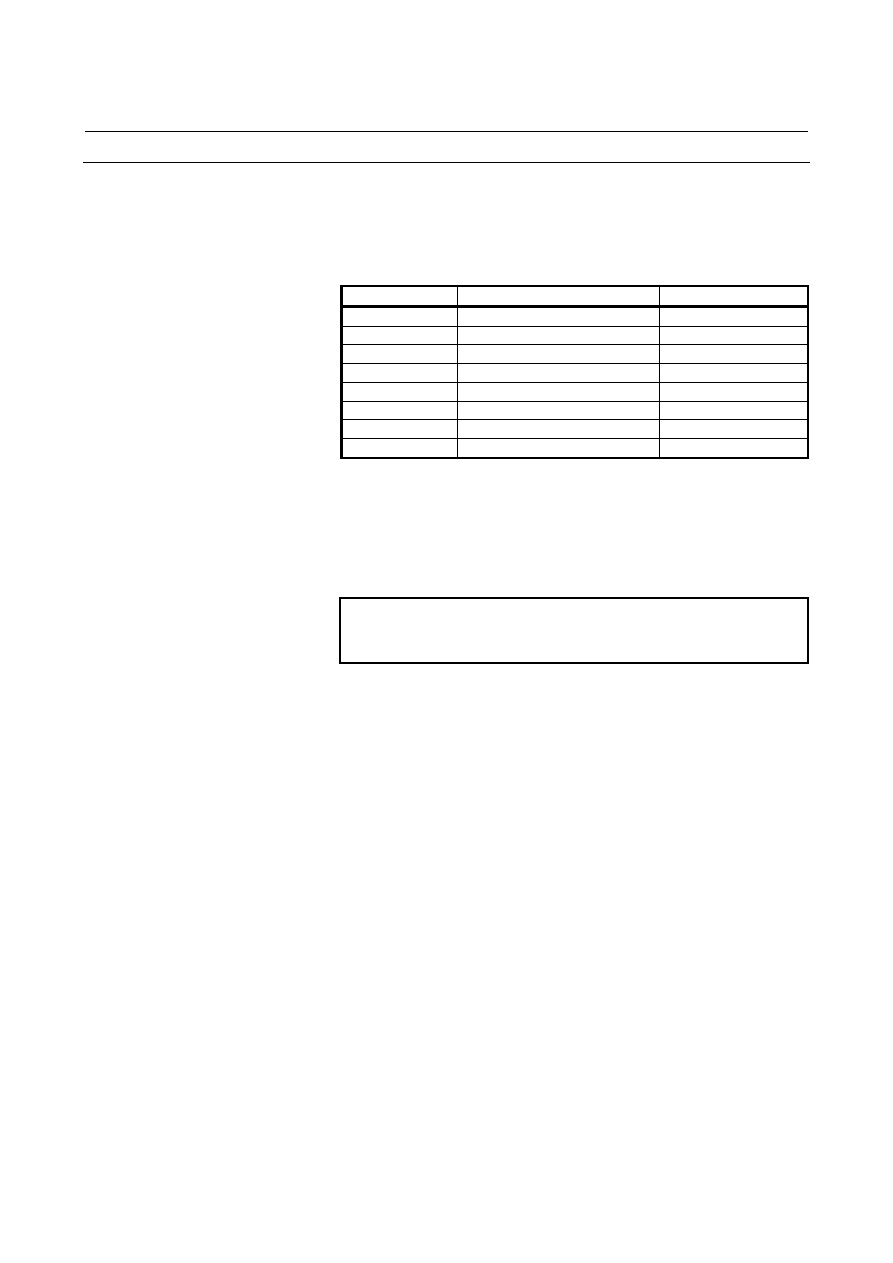
To select operation level 0 to 3, use the corresponding memory
protection key signal.
To select operation level 4 to 7, use the corresponding password.
Table 12.3.11.1 (a) Operation level setting
Operation level
Setting
Sample grouping
7 (high)
Password
-
6 Password
MTB
5
Password
Dealer and integrator
4 Password
End
user
3
Memory protection key signal
User level (level 1)
2
Memory protection key signal
User level (level 2)
1
Memory protection key signal
User level (level 3)
0 (low)
Memory protection key signal
User level (level 4)
When operation level 4 to 7 is set, the operation level remains
unchanged until the password is cleared.
(The operation level also remains unchanged if the power is turned
off.)
Operation level 7 is reserved for CNC and PMC maintenance.
NOTE
When a password is being entered, an asterisk (*)
is displayed instead of each entered character.
12.SETTING AND DISPLAYING DATA
OPERATION
B-63944EN/03
- 1616 -
12.3.11.2
Password modification
The current operation level is displayed.
The password for each of operation levels 4 to 7 can be modified.
Displaying and setting the password modification screen
Procedure
1
Press function key
.
2
Press the continuous menu key
several times until soft key
[PROTECT] is displayed.
3
Press soft key [PROTECT].
4
Press soft key [PASSWORD].
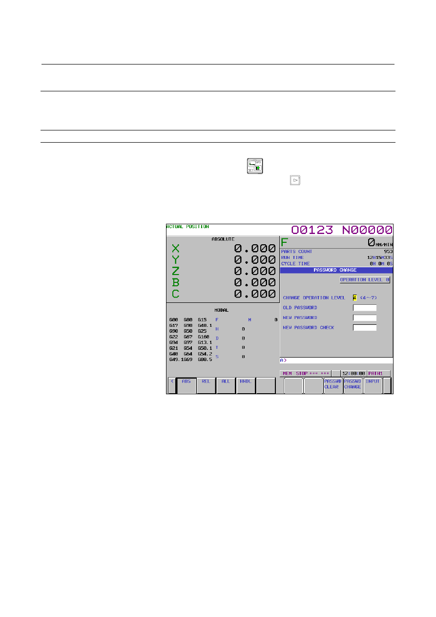
The PASSWORD CHANGE screen shown below is displayed.
Fig. 12.3.11.2 (a) PASSWORD CHANGE screen (10.4-inch)
5
Key in an operation level whose password is to be modified, then
press soft key [INPUT].
6 Key in the current password for the operation level whose
password is to be modified, then press soft key [INPUT].
7
Key in a new password, then press soft key [INPUT].
8
Key in the new password again for confirmation, then press soft
key [INPUT].
9
Press soft key [PASSWDCHANGE].
10 To clear the password, press soft key [PASSWDCLEAR].
B-63944EN/03
OPERATION
12.SETTING AND DISPLAYING DATA
- 1617 -
Explanation
Up to eight characters (only uppercase alphabetic characters and
numeric characters) can be input.
NOTE
1 For a password, consisting of three to eight
characters, the following characters are available:
•
Uppercase alphabetic characters
•
Numeric characters
2 When a password is being entered, an asterisk (*)
is displayed instead of each entered character.
3 Whether a password can be changed at the current
operation level is determined as follows:
•
Password of an operation level higher than the
current operation level
Cannot be changed.
•
Password of the current operation level
Can be changed.
•
Password of an operation level lower than the
current operation level
Can be changed (only to the initial password).
4 The set password is not displayed.
Be careful not to forget the password.
12.SETTING AND DISPLAYING DATA
OPERATION
B-63944EN/03
- 1618 -
12.3.11.3
Protection level setting
The current operation level is displayed.
The change protection level and output protection level of each data
item are displayed.
The change protection level and output protection level of each data
item can be changed.
Confirmation based on protection level setting
Procedure
1
Press function key
.
2
Press the continuous menu key
several times until soft key
[PROTECT] is displayed.
3
Press soft key [PROTECT].
4
Press soft key [DATA LEVEL] to change the protection level of
CNC data or press soft key [PMC LEVEL] to change the
protection level of PMC data.
The following protection level change screen is displayed.
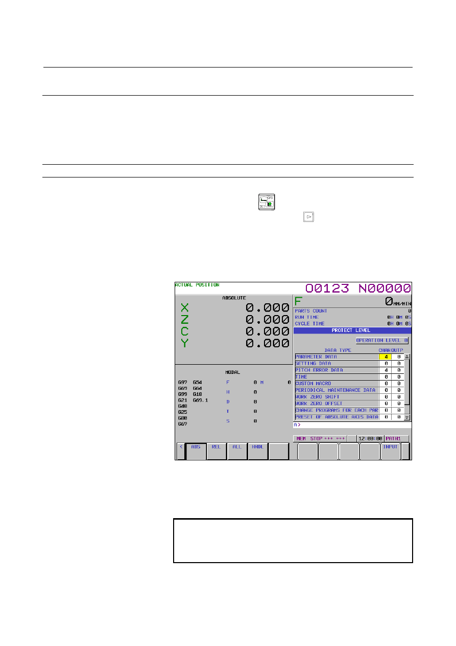
Fig. 12.3.11.3 (a) Protection level change screen (10.4-inch)
5
Move the cursor to the change level or output level of a desired
data item.
6
Key in a new desired level, then press soft key [INPUT].
NOTE
When the protection level of PMC data is set, soft
key [SWITCH PMC] is used to switch between
PMC paths to be set, for multipath PMC.
B-63944EN/03
OPERATION
12.SETTING AND DISPLAYING DATA
- 1619 -
Explanation
When the protection level of a data item is higher than the current
operation level, the protection level of the data item cannot be
changed.
The protection level of a data item cannot be changed to a protection
level higher than the current operation level.
For each of the following types of data, you can set a data protection
level. There are the following two types of data protection levels:
•
Change protection level
Sets the protection level used when data is changed.
•
Output protection level
Sets the protection level used when data is output (punched out) to an
external unit.
As a protection level, you can set a value of 0 (low) to 7 (high).
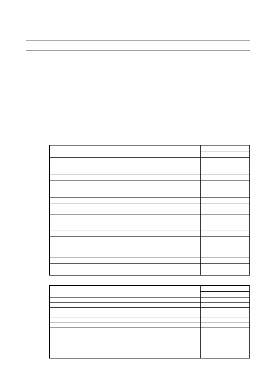
Table 12.3.11.3 (a) Protection level of each type of data
Initial protection level
Type of data
Change Output
Custom macro variable data <CUSTOM MACRO>
(including variable data dedicated to the macro executor)
0 0
Periodical maintenance data <PERIODICAL MAINTENANCE DATA>
0 0
Tool management data <TOOL LIFE TIME DATA>
0 0
Tool offset data <TOOL OFFSET DATA>
(For each type when tool geometry compensation and tool wear compensation
are treated differently)
0 0
Clock data <TIME>
0 0
Workpiece origin shift amount data <WORK ZERO SHIFT>
0 0
Workpiece origin offset data <WORK ZERO OFFSET>
0 0
Ethernet setting data <ETHER NET SETTING>
0
0
Fixture offset data <FIXTURE OFFSET DATA>
0
0
Parameter data <PARAMETER DATA>
4 0
Settings <SETTING DATA>
0 0
Pitch error compensation data <PITCH ERROR DATA>
(including three-dimensional error compensation data)
4 0
Parameter data for Power Mate CNC manager function
<PARAMETER DATA FOR POWER MATE CNC MANAGER>
0 0
Each part program <PROGRAMS FOR EACH PARTS>
0 0
Part program editing operation <CHANGE PROGRAMS FOR EACH PARTS>
0 0
Absolute coordinate preset operation <PRESET OF ABSOLUTE AXIS DATA>
0 0
Table 12.3.11.3 (b) Protection level of PMC data
Initial protection level
Type of data
Change Output
Composition parameter
0
0
Setting (online)
0
0
Setting (each path)
0
0
Sequence program
0
0
PMC parameter
0
0
Timer
0 0
Counter
0 0
Keep relay
0 0
Keep relay (system)
0
0
Data table
0 0
Data table control
0
0
PMC momory
0
0
Нет комментариевНе стесняйтесь поделиться с нами вашим ценным мнением.
Текст