
FANUC Series 30i/300i/300is-MODEL A. Machining Center System. User's manual — page 276
A.PARAMETERS
APPENDIX
B-63944EN/03
- 2164 -
7710
Axis number of an axis to be synchronized using the method of command
specification for a hobbing machine
NOTE
When this parameter is set, the power must be
turned off before operation is continued.
[Input type] Parameter input
[Data type] 2-word path
[Valid data range] 1 to Number of controlled axes
When there are several groups of axes to be synchronized (the axes for
which bit 0 (SYNMOD) of parameter No. 2011 is set to 1), an axis for
which to start synchronization is specified using the following
command (for a hobbing machine):
G81 T t L ±
l
;
t: Spindle speed (1
≤
t
≤
1000)
l
: Number of synchronized axis rotations (1
≤
l
≤
21)
Synchronization between the spindle and a specified axis is
established with the ratio of
±
l
rotations about the synchronized axis
to t spindle rotations.
t and
l
correspond to the number of teeth and the number of threads on
the hobbing machine, respectively.
Above command is issued without setting this parameter when there
are several groups of axes to be synchronized, the alarm (PS1593) is
issued.
When only one group of axes is to be synchronized, this parameter is
ignored.
#7 #6 #5 #4 #3 #2 #1 #0
7731
ECN
EFX
[Input type] Parameter input
[Data type] Bit path
# 0
EFX
As the EGB command:
0: G80 and G81 are used.
1: G80.4 and G81.4 are used.
NOTE
When this parameter is set to 0, no drilling canned
cycle can be used.
# 3
ECN
When the automatic phase synchronization function for the electronic
gear box is disabled, during EGB synchronization, the G81 or G81.5
command:
0: Cannot be issued again. (The alarm (PS1595) is issued.)
1: Can be issued again.
B-63944EN/03
APPENDIX
A.PARAMETERS
- 2165 -
7740
Feedrate during retraction
[Input type] Parameter input
[Data type] Real axis
[Unit of data] mm/min, inch/min, degree/min (machine unit)
[Minimum unit of data] Depend on the increment system of the applied axis
[Valid data range] Refer to the standard parameter setting table (C)
(When the increment system is IS-B, 0.0 to +999000.0)
This parameter sets the feedrate during retraction for each axis.
7772
Number of position detector pulses per rotation about the tool axis
[Input type] Parameter input
[Data type] 2-word path
[Valid data range] 1 to 999999999
This parameter sets the number of pulses per rotation about the tool
axis (on the spindle side), for the position detector.
For an A/B phase detector, set this parameter with four pulses
equaling one A/B phase cycle.
7773
Number of position detector pulses per rotation about the workpiece axis
[Input type] Parameter input
[Data type] 2-word path
[Valid data range] 1 to 999999999
This parameter sets the number of pulses per rotation about the
workpiece axis (on the slave side), for the position detector.
Set the number of pulses output by the detection unit.
Set parameters Nos. 7772 and 7773 when using the G81 EGB
synchronization command.
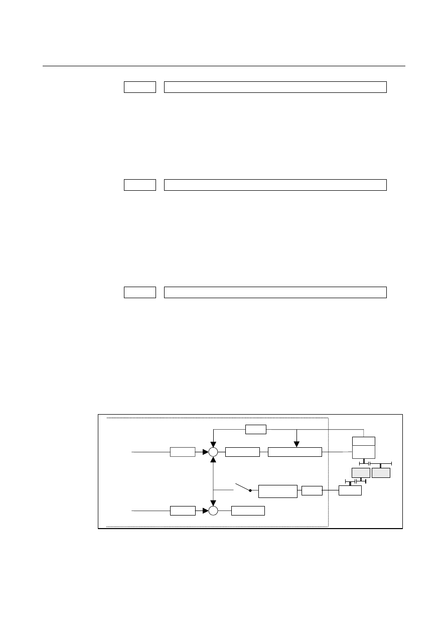
[Example 1] When the EGB master axis is the spindle and the EGB slave axis is
the C-axis
Synchronization
switch
CNC
Detection unit
β
p/rev
α
p/rev
C-axis
Least command increment
0.001deg
Command
pulses
×
FFG
Gear ratio
A
Detector
×
CMR
Slave axis
Gear
ratio B
Error counter
Follow-up
×
CMR
Dummy axis
n/m
×
FFG
N/M
Motor
Detector
Spindle
Error counter
Speed/current control
Synchronization
factor
Gear ratio of the spindle to the detector B:
1/1 (The spindle and detector are directly connected to each
other.)
Number of detector pulses per spindle rotation
β
: 80,000 pulses/rev
(Calculated for four pulses for one A/B phase cycle)

A.PARAMETERS
APPENDIX
B-63944EN/03
- 2166 -
FFG N/M of the EGB dummy axis: 1/1
Gear ratio of the C-axis A: 1/36 (One rotation about the C-axis to 36
motor rotations)
Number of detector pulses per C-axis rotation
α
: 1,000,000 pulses/rev
C-axis CMR:
1
C-axis FFG n/m:
1/100
In this case, the number of pulses per spindle rotation is:
80000
×
1/1 = 80000
Therefore, set 80000 for parameter No. 7772.
The number of pulses per C-axis rotation in the detection unit is:
1000000
÷
1/36
×
1/100 = 360000
Therefore, set 360000 for parameter No. 7773.
[Example 2] When the gear ratio of the spindle to the detector B is 2/3 for the
above example (When the detector rotates twice for three spindle
rotations)
In this case, the number of pulses per spindle rotation is:
3
160000
=
3
2
80000
×
160000 cannot be divided by 3 without a remainder. In this case,
change the setting of parameter No. 7773 so that the ratio of the
settings of parameters Nos. 7772 and 7773 indicates the value you
want to set.
1080000
160000
=
3
360000
160000
=
360000
3
160000
=
No.7773
No.7772
×
Therefore, set 160000 for parameter No. 7772 and 1080000 for
parameter No. 7773.
As described above, all the settings of parameters Nos. 7772 and 7773
have to do is to indicate the ratio correctly. So, you can reduce the
fraction indicated by the settings. For example, you may set 16 for
parameter No. 7772 and 108 for parameter No. 7773 for this case.
7776
Feedrate during automatic phase synchronization for the workpiece axis
[Input type] Parameter input
[Data type] Real path
[Unit of data] deg/min
[Minimum unit of data] Depend on the increment system of the applied axis
[Valid data range] Refer to the standard parameter setting table (C)
(When the increment system is IS-B, 0.0 to +999000.0)
This parameter sets the feedrate during automatic phase
synchronization for the workpiece axis.
When this parameter is set to 0, the rapid traverse rate (parameter No.
1420) is used as the feedrate during automatic phase synchronization.

B-63944EN/03
APPENDIX
A.PARAMETERS
- 2167 -
7777
Angle shifted from the spindle position (one-rotation signal position) which
the workpiece axis uses as the reference of phase synchronization
[Input type] Parameter input
[Data type] Real path
[Unit of data] deg
[Minimum unit of data] Depend on the increment system of the applied axis
[Valid data range] 9 digit of minimum unit of data (refer to standard parameter setting
table (A))
(When the increment system is IS-B, -999999.999 to +999999.999)
This parameter sets the angle shifted from the spindle position
(one-rotation signal position) which the workpiece axis uses as the
reference of phase synchronization.
7778
Acceleration for acceleration/deceleration for the workpiece axis
[Input type] Parameter input
[Data type] Real axis
[Unit of data] deg/sec
2
[Minimum unit of data] Depend on the increment system of the applied axis
[Valid data range] Refer to the standard parameter setting table (D)
(For a millimeter machine, 0.0 to +100000.0, for an inch machine, 0.0
to +10000.0)
This parameter sets an acceleration for acceleration/deceleration for
the workpiece axis.
NOTE
1 In the FS16
i
series, acceleration/deceleration for
automatic phase matching is set by specifying a
feedrate and a time constant in parameter Nos.
2135 and 2136 separately; in the FS30i series,
acceleration/deceleration is directly set in
parameter No. 7778.
2 If this parameter is set to 0, specifying G81 results
in an alarm (PS1598).
7782
Number of pulses from the position detector per EGB master axis rotation
[Input type] Parameter input
[Data type] 2-word axis
[Valid data range] 1 to 999999999
For a slave axis, set the number of pulses generated from the position
detector per EGB master axis rotation.
For an A/B phase detector, set this parameter with four pulses
equaling one A/B phase cycle.
A.PARAMETERS
APPENDIX
B-63944EN/03
- 2168 -
7783
Number of pulses from the position detector per EGB slave axis rotation
[Input type] Parameter input
[Data type] 2-word axis
[Unit of data] Detection unit
[Valid data range] 1 to 999999999
For a slave axis, set the number of pulses generated from the position
detector per EGB slave axis rotation.
Set the number of pulses output by the detection unit.
Set this parameter when using the G81.5 EGB synchronization
command.
The method for setting parameters Nos. 7782 and 7783 is the same as
for parameters Nos. 7772 and 7773. For the method, see the
description of parameters Nos. 7772 and 7773.
The ratio of the number of pulses for the master slave to that of pulses
for the slave axis may be valid, but the settings of the parameters may
not indicate the actual number of pulses. For example, the number of
pulses may not be able to be divided without a remainder for the
reason of the master and slave axis gear ratios as described in example
2. In this case, the following methods cannot be used for the G81.5
command:
G81.5 T_ C_
; When the speed is specified for the master axis and
the travel distance is specified for the slave axis
G81.5 P_ C0 L_ ; When the number of pulses is specified for the
master axis and the speed is specified for the slave
axis
#7 #6 #5 #4 #3 #2 #1 #0
8001
RDE
OVE
MLE
[Input type] Parameter input
[Data type] Bit path
# 0
MLE
Whether all axis machine lock signal MLK is valid for
PMC-controlled axes
0: Valid
1: Invalid
The axis-by-axis machine lock signal MLKx depends on the setting of
bit 1 of parameter No. 8006.
B-63944EN/03
APPENDIX
A.PARAMETERS
- 2169 -
# 2
OVE
Signals related to dry run and override used in PMC axis control
0: Same signals as those used for the CNC
1: Signals specific to the PMC
The signals used depend on the settings of these parameter bits as
indicated below.
Signals
No.8001#2=0
(same signals as those used for the CNC)
No.8001#2=1
(signals specific to the PMC)
Feedrate override signals
*FV0 to *FV7
G012
*EFV0 to *EFV7
G151
Override cancellation signal OVC
G006. EOVC
G150.5
Rapid traverse override signals ROV1,2
G014.0, .1
EROV1,2
G150.0, .1
Dry run signal
DRN
G46.7 EDRN
G150.7
Rapid traverse selection signal
RT G19.7
ERT
G150.6
(The signal addresses at PMC selection time are for the first group.)
# 3
RDE
Whether dry run is valid for rapid traverse in PMC axis control
0: Invalid
1: Valid
#7 #6 #5 #4 #3 #2 #1 #0
8002 FR2 FR1 PF2 PF1 F10
RPD
[Input type] Parameter input
[Data type] Bit path
# 0
RPD
Rapid traverse rate for PMC-controlled axes
0: Feedrate specified with parameter No.1420
1: Feedrate specified with the feedrate data in an axis control
command by PMC
# 3
F10
Least increment for the feedrate for cutting feed (per minute) in PMC
axis control
The following settings are applied when bit 4 (PF1) of parameter No.
8002 is set to 0 and bit 5 (PF2) of parameter No. 8002 is set to 0.
F10
IS-A
IS-B
IS-C
IS-D
IS-E
0
10
1
0.1 0.01 0.001
Millimeter input
(mm/min)
1
100
10
1 0.1 0.01
0
0.1
0.01
0.001 0.0001 0.00001
Inch input
(inch/min)
1
1
0.1
0.01 0.001 0.0001
# 4
PF1
# 5
PF2
Set the feedrate unit of cutting feedrate (feed per minute) for an axis
controlled by the PMC.
Bit 5 (PF2) of parameter
No. 8002
Bit 4 (PF1) of parameter
No. 8002
Feedrate unit
0
0
1 / 1
0
1
1 / 10
1
0
1 / 100
1
1
1 / 1000
A.PARAMETERS
APPENDIX
B-63944EN/03
- 2170 -
# 6
FR1
# 7
FR2
Set the feedrate unit for cutting feedrate (feed per rotation) for an axis
controlled by the PMC.
Bit 7 (FR2) of
parameter No. 8002
Bit 6 (FR1) of
parameter No. 8002
Millimeter
input
(mm/rev)
Inch input
(inch/rev)
0 0
1 1
0.0001 0.000001
0 1
0.001
0.00001
1 0
0.01
0.0001
#7 #6 #5 #4 #3 #2 #1 #0
8004
NCI
[Input type] Parameter input
[Data type] Bit path
# 6
NCI
In axis control by the PMC, a position check at the time of
deceleration is:
0: Performed.
1: Not
performed.
#7 #6 #5 #4 #3 #2 #1 #0
8005
EDC
[Input type] Setting input
[Data type] Bit path
# 0
EDC
In axis control by the PMC, an external deceleration function is:
0: Disabled.
1: Enabled.
#7 #6 #5 #4 #3 #2 #1 #0
8006
EZR EFD
[Input type] Parameter input
[Data type] Bit path
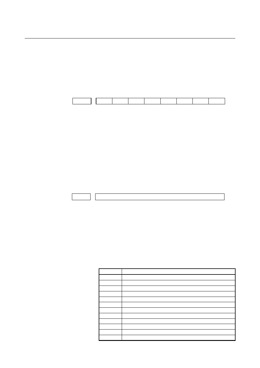
# 4
EFD
When cutting feed (feed per minute) is used in PMC axis control, the
specification unit of feedrate data is:
0: Unchanged (1 times).
1: 100 times greater.
NOTE
When this parameter is set to 1, bit 3 (F10) of
parameter No. 8002 is invalid.
B-63944EN/03
APPENDIX
A.PARAMETERS
- 2171 -
# 6
EZR
In PMC axis control, bit 0 (ZRNx) of parameter No. 1005 is:
0: Invalid.
With a PMC controlled axis, the alarm (PS0224) is not issued.
1: Valid.
A reference position return state check is made on a PMC
controlled axis as with an NC axis according to the setting of bit
0 (ZRNx) of parameter No. 1005.
#7 #6 #5 #4 #3 #2 #1 #0
8008
EMRx
[Input type] Parameter input
[Data type] Bit axis
# 0
EMRx
When a PMC axis control command is issued in mirror image state,
the mirror image is:
0: Not
considered.
1: Considered.
This parameter is valid in the mirror image mode set with the mirror
image signals MI1 to MI8 <G106.0 to .7> set to 1 or bit 0 (MIRx) of
parameter No. 12 set to 1.
If a movement is made along the same axis by doubly specifying a
command with the CNC and PMC axis control when this parameter is
set to 0, and the mirror image mode is set, a coordinate shift can occur
afterwards. So, do not attempt to make such a movement.
8010
Selection of the DI/DO group for each axis controlled by the PMC
[Input type] Parameter input
[Data type] Byte axis
[Valid data range] 1 to 40
Specify the DI/DO group to be used to specify a command for each
PMC-controlled axis.
For addresses of the fifth group and up, 1000 is added in steps of 4
groups.
For example:
The start address of the 10th group is G2154.
The start address of the 25th axis is G6142.
P8010 Description
1
DI/DO 1st group (G142 to G153) is used.
2
DI/DO 2nd group (G154 to G165) is used.
3
DI/DO 3rd group (G166 to G177) is used.
4
DI/DO 4th group (G178 to G189) is used.
5
DI/DO 5th group (G1142 to G1153) is used.
6
DI/DO 6th group (G1154 to G1165) is used.
: :
13
DI/DO 13th group (G3142 to G3153) is used.
: :
20
DI/DO 20th group (G4178 to G4189) is used.
21
DI/DO 21st group (G5142toG5153) is used.
: :
Нет комментариевНе стесняйтесь поделиться с нами вашим ценным мнением.
Текст