
Hyundai Excavator R450LC-7. Service and repair manual — page 15
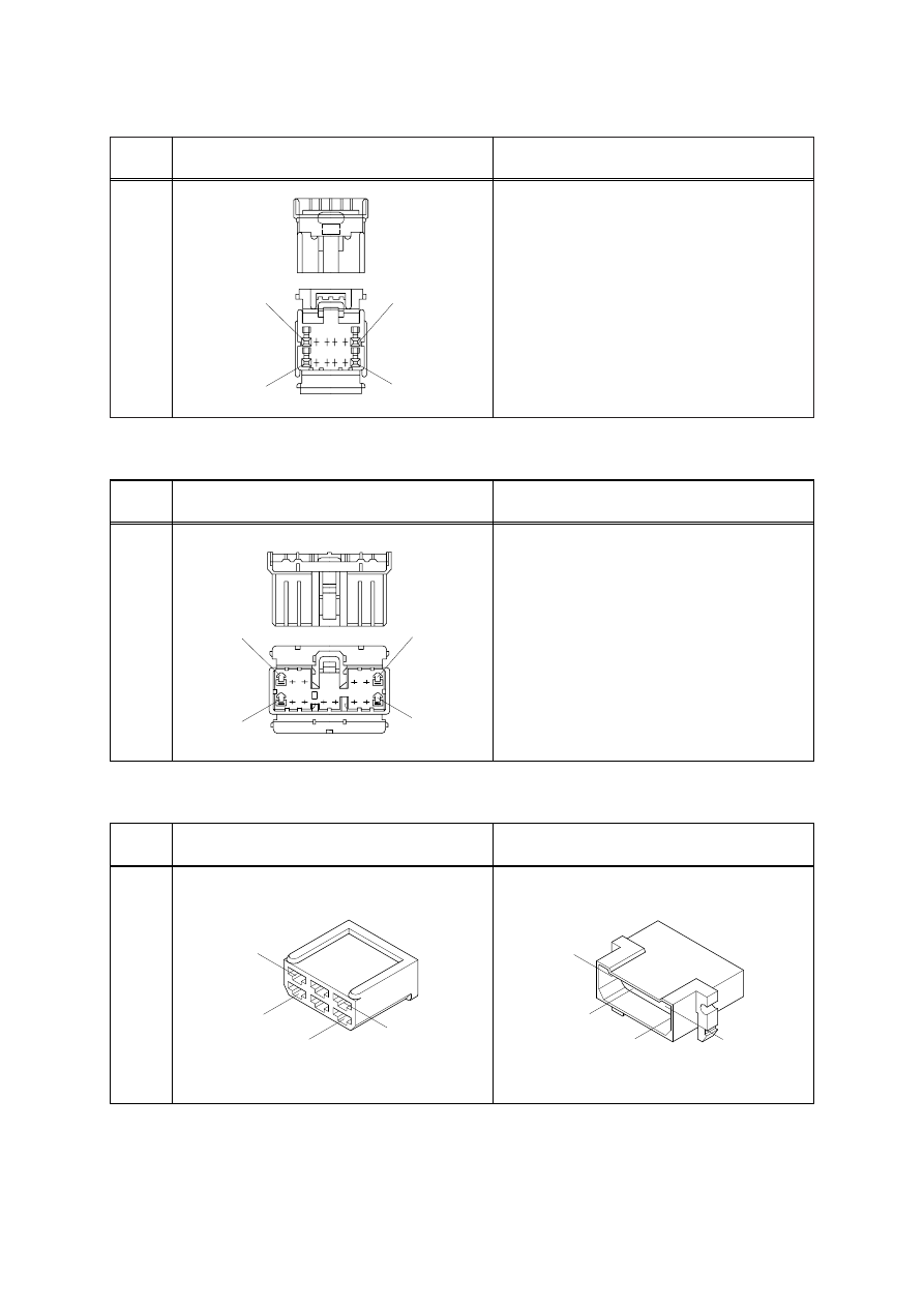
4-39
No. of
pin
Receptacle connector(Female)
Plug connector(Male)
12
1
7
6
12
174045-2
AMP 040 MULTILOCK CONNECTOR
8)
No. of
pin
Receptacle connector(Female)
Plug connector(Male)
14
1
7
6
14
173852
AMP 070 MULTILOCK CONNECTOR
9)
No. of
pin
Receptacle connector(Female)
Plug connector(Male)
6
3
6
1
4
925276-0
1
4
3
6
480003-9
AMP FASTIN - FASTON CONNECTOR
10)
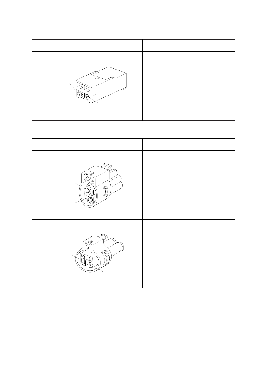
4-40
No. of
pin
Receptacle connector(Female)
Plug connector(Male)
2
1
2
MG610070
KET 090 CONNECTOR
11)
No. of
pin
Receptacle connector(Female)
Plug connector(Male)
2
2
1
2
1
2
MG640605
MG640795
KET 090 WP CONNECTORS
12)
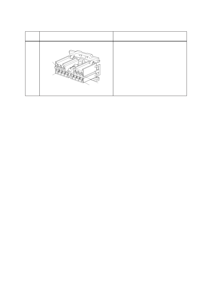
4-41
No. of
pin
Receptacle connector(Female)
Plug connector(Male)
14
1
7
6
14
MG610406
KET SDL CONNECTOR
13)
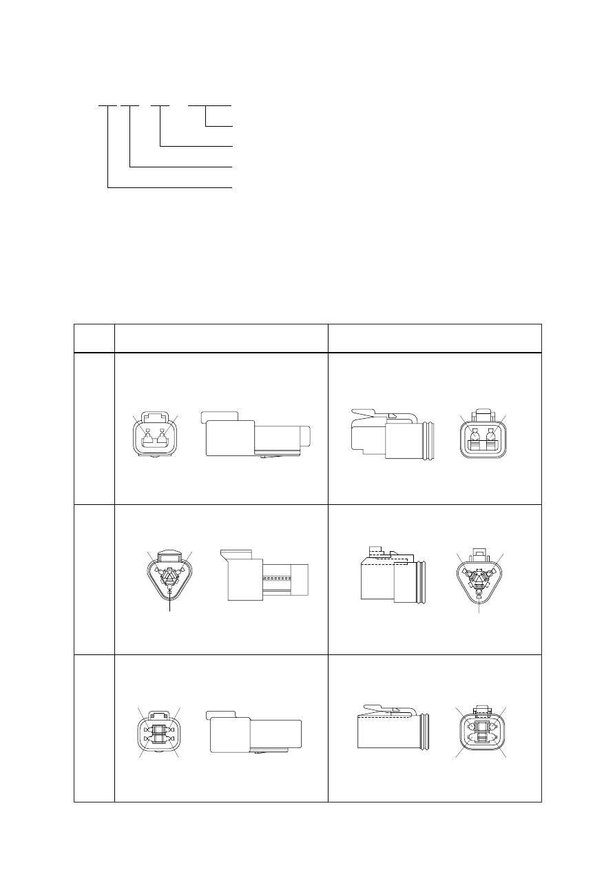
4-42
No. of
pin
Receptacle connector(Female)
Plug connector(Male)
2
1
2
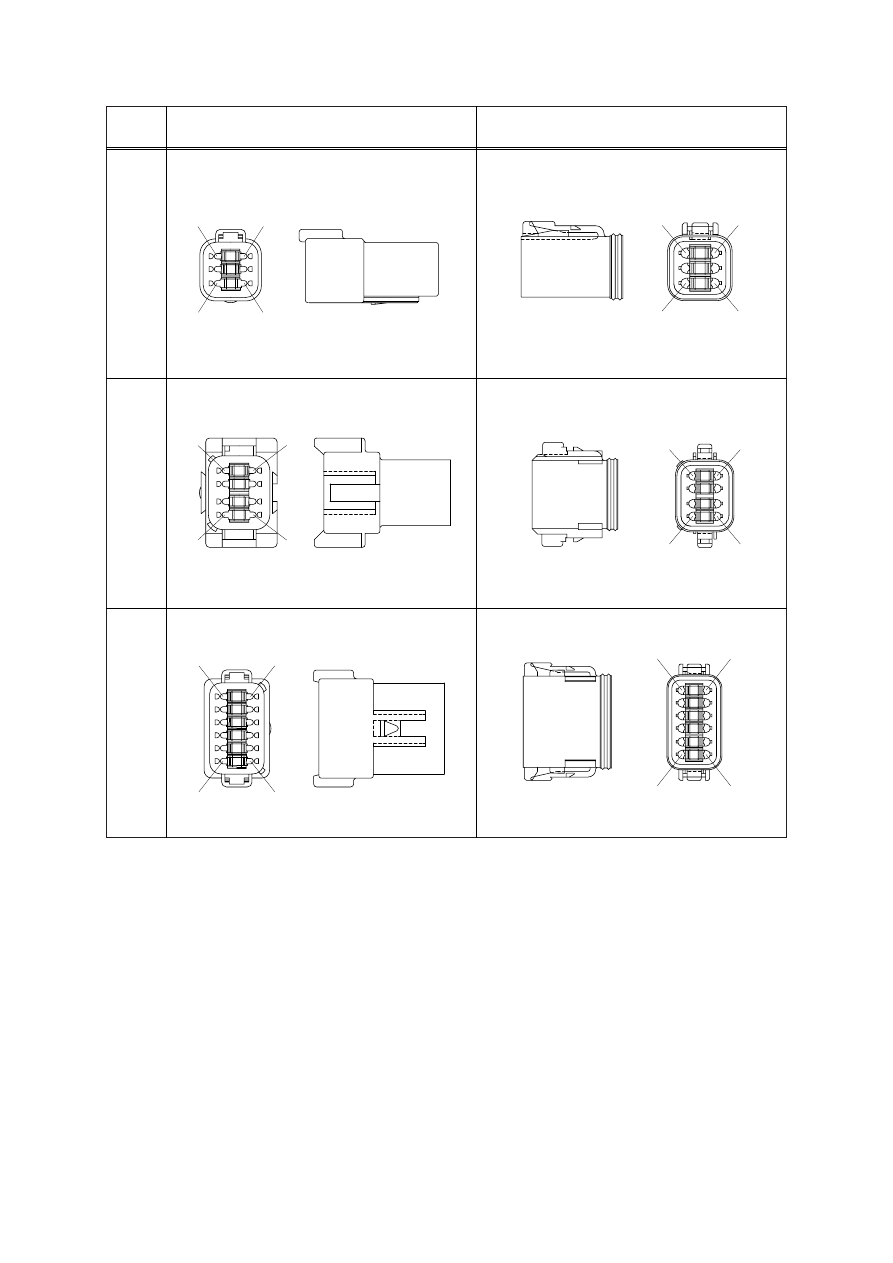
DT06-2S
3
1
2
DT04-2P
2
1
3
DT06-3S
2
1
3
DT04-3P
DEUTSCH DT CONNECTORS
DT 06 - 3S -
★★★★
14)
Modifications(See below)
Number of contacts(P : Pin, S : Socket)
04 : Receptacle, 06 : Plug
Deutsch connetors
Modification
E003 : Standard end cap - gray
E004 : Color of connector to be black
E005 : Combination - E004 & E003
EP04 : End cap
EP06 : Combination P012 & EP04
P012 : Front seal enhancement - connectors color to black for 2, 3, 4 & 6pin
※
4
4
2
3
1
DT06-4S
4
1
3
2
DT04-4P
4-43
No. of
pin
Receptacle connector(Female)
Plug connector(Male)
6
6
1
4
3
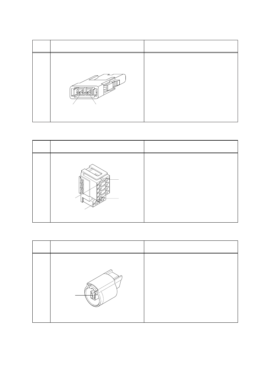
DT06-6S
6
1
4
3
DT04-6P
5
4
8
1
8
5
4
8
1
DT06-8S
12
DT04-8P
6
7
1
12
DT06-12S
7
6
12
1
DT04-12P
4-44
No. of
pin
Receptacle connector(Female)
Plug connector(Male)
2
1
2
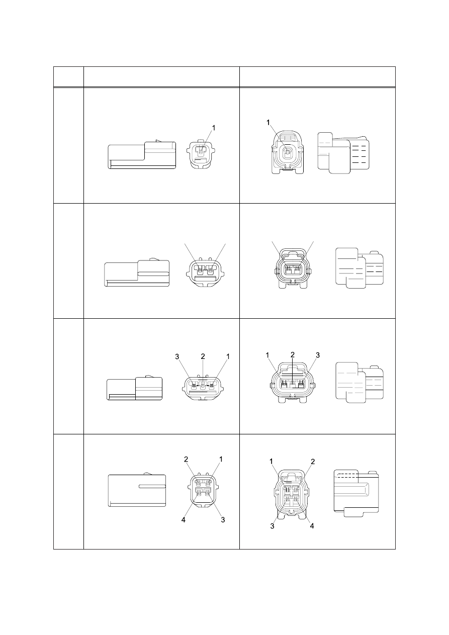
35215-0200
MOLEX 2CKTS CONNECTOR
15)
No. of
pin
Receptacle connector(Female)
Plug connector(Male)
10
1
2
9
10
SWF593757
ITT SWF CONNECTOR
16)
No. of
pin
Receptacle connector(Female)
Plug connector(Male)
1
1
NMWP01F-B
MWP NMWP CONNECTOR
17)
4-45
No. of
pin
Receptacle connector(Female)
Plug connector(Male)
1
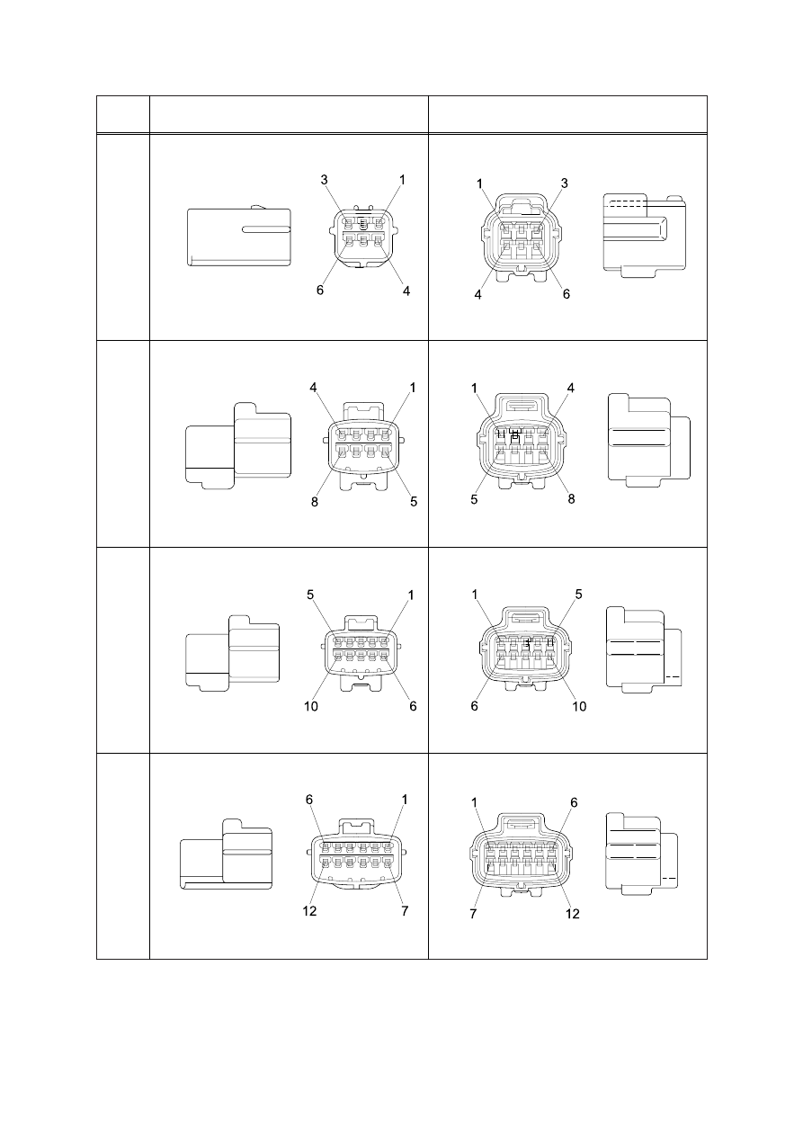
S816-001002
2
3
4
S816-101002
2
1
S816-002002
2
1
S816-102002
S816-003002
S816-103002
S816-004002
S816-104002
ECONOSEAL J TYPE CONNECTORS
18)
4-46
No. of
pin
Receptacle connector(Female)
Plug connector(Male)
6
S816-006002
8
10
12
S816-106002
S816-008002
S816-108002
S816-010002
S816-110002
S816-012002
S816-112002
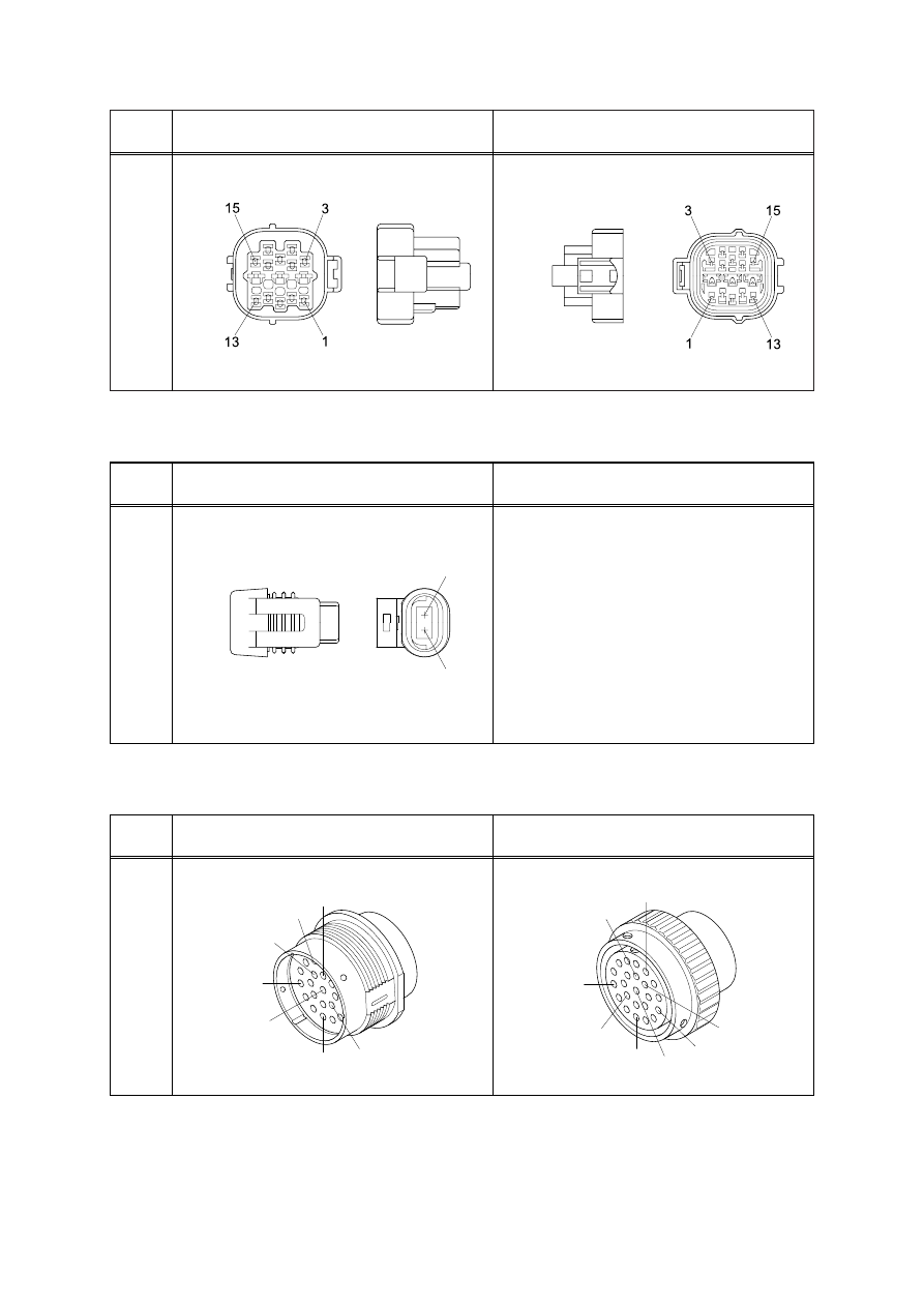
4-47
No. of
pin
Receptacle connector(Female)
Plug connector(Male)
15
368301-1
2-85262-1
No. of
pin
Receptacle connector(Female)
Plug connector(Male)
2
1
2
12040753
METRI-PACK TYPE CONNECTOR
19)
No. of
pin
Receptacle connector(Female)
Plug connector(Male)
23
A
B
F
J
K
N
Q
HD36-24-23SN
A
B
F
K
Q
J
N
T
HD34-24-23PN
DEUTSCH HD30 CONNECTOR
20)

SECTION 5 MECHATRONICS SYSTEM
Group 1 Outline
5-1
Group 2 Mode Selection System
5-3
Group 3 Automatic Deceleration System
5-6
Group 4 Power Boost System
5-7
Group 5 Travel Speed Control System
5-8
Group 6 Automatic Warming Up Function
5-9
Group 7 Engine Overheat Prevention Function
5-10
Group 8 Anti-Restart System
5-11
Group 9 Self-Diagnostic System
5-12
Group 10 Engine Control System
5-20
Group 11 EPPR(Electro Proportional Pressure Reducing) Valve
5-22
Group 12 Monitoring System
5-25
5-1
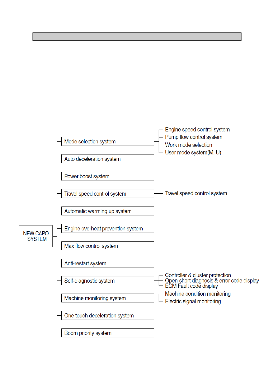
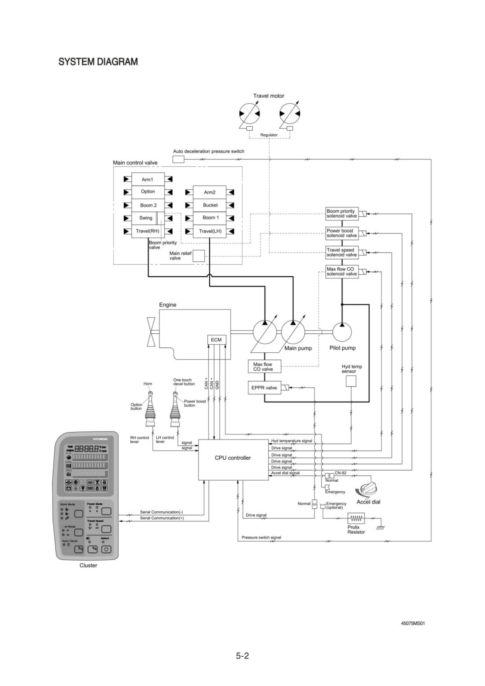
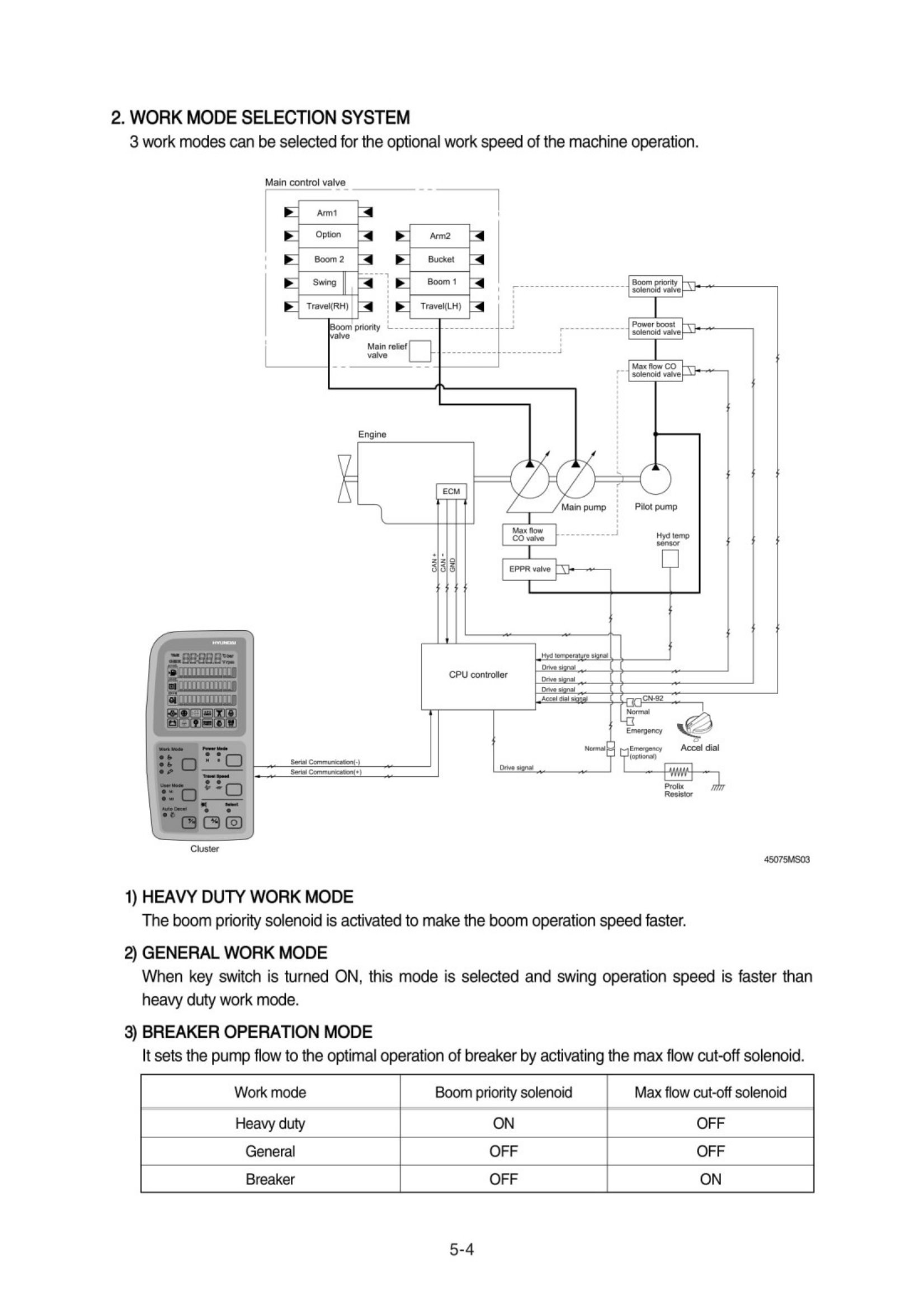
The NEW CAPO(Computer Aided Power Optimization) system controls engine and pump mutual power
at an optimum and less fuel consuming state for the selected work by mode selection, auto-
deceleration, power boost function, etc. It monitors machine conditions, for instance, engine speed,
coolant temperature, hydraulic oil temperature, and hydraulic oil pressure, etc.
It consists for a CPU controller, a cluster, an electronic control module (ECM), an EPPR valve, and other
components. The CPU controller and the cluster protect themselves from over-current and high voltage
input, and diagnose malfunctions caused by short or open circuit in electric system, and display error
codes on the cluster.
SECTION 5 MECHATRONICS SYSTEM
GROUP 1 OUTLINE
5-5
To memorize the final setting, press the USER
mode switch and SELECT switch one more time.
5)
1
2
3
4
5
6
7
8
9
10
Segment
( )
High idle-900
High idle-800
High idle-700
High idle-600
High idle-500
High idle-400
High idle-300
High idle-200
High idle-100
High idle
ACCEL
(rpm)
Low idle(800)
850
900
950
Decel rpm(1000)
1050
1100
1150
1200
1250
DECEL
(rpm)
150
200
250
300
350
400
450
500
550
600
EPPR
(mA)
36075MS03C
3. USER MODE SELECTION SYSTEM
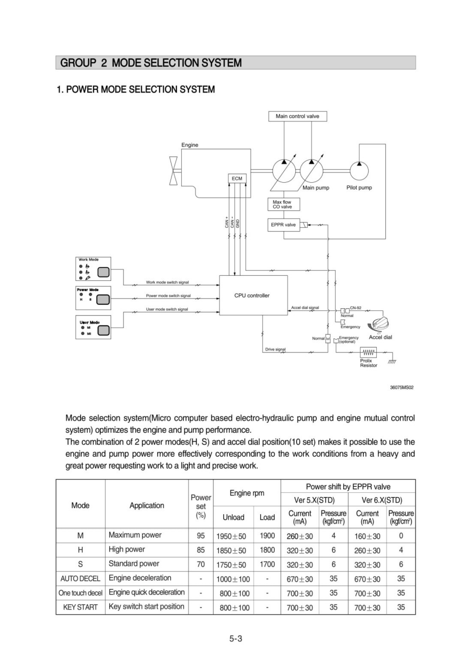
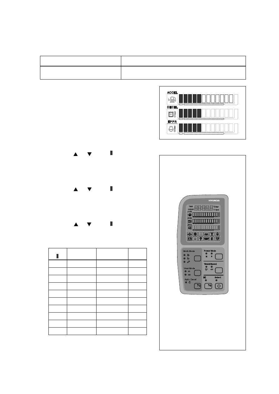
Through 2 memory sets of MI and MII, an operator can change the engine and pump power and
memorize it for his preference.
Mode
Operation
U
High idle rpm, auto decel rpm
EPPR pressure can be modulated and memorized separately
HOW TO MODULATE THE MEMORY SET
Each memory mode has a initial set which are
mid-range of max engine speed, auto decel rpm,
and EPPR valve input current. When you select
"U", cluster LCD displays.
To change the engine high idle speed, press the
USER mode switch and SELECT switch at the
same time and then ACCEL blinks at 0.5 seconds
interval.
- By pressing or switch, will increase or
decrease.
To change DECEL rpm, press the USER mode
switch and SELECT switch once more and then
DECEL blinks at 0.5 seconds interval.
- By pressing or switch, will increase or
decrease.
To change EPPR current, press the USER mode
switch and SELECT switch one more and then
EPPR blinks at 0.5 seconds interval.
- By pressing or switch, will increase or
decrease.
·
LCD segment vs parameter setting
1)
2)
3)
4)
140W74OP03G
Нет комментариевНе стесняйтесь поделиться с нами вашим ценным мнением.
Текст