
FANUC Series 0i-MODEL F Plus. CONNECTION MANUAL (FUNCTION) — page 231
10. SPINDLE SPEED FUNCTION
B-64693EN-1/01
- 1802 -
3717
Spindle amplifier number to each spindle
NOTE
When this parameter is set, the power must be turned off before
operation is continued.
[Input type] Parameter input
[Data type] Byte spindle
[Valid data range] 0 to Maximum number of controlled axes
Set a spindle amplifier number to be assigned to each spindle.
0:
No spindle amplifier is connected.
1:
Spindle motor connected to amplifier number 1 is used.
2:
Spindle motor connected to amplifier number 2 is used.
to
n:
Spindle motor connected to amplifier number n is used.
3718
Subscript for display of a serial spindle (main spindle) or analog spindle
[Input type] Parameter input
[Data type] Byte spindle
[Valid data range] 0 to 122
Set a subscript to be added to spindle speed display on a screen such as the position
display screen.
Used when the spindle switching function is not used, or used for the main spindle when
the spindle switching function is used.
NOTE
This parameter is invalid when an extended spindle name is used.
3719
Subscript for display of a serial spindle (sub-spindle)
[Input type] Parameter input
[Data type] Byte spindle
[Valid data range] 0 to 122
Set a subscript to be added to spindle speed display on a screen such as the position
display screen.
Used for the sub-spindle when the spindle switching function is used.
NOTE
This parameter is invalid when an extended spindle name is used.
3741
Maximum spindle speed for gear 1
3742
Maximum spindle speed for gear 2
3743
Maximum spindle speed for gear 3
3744
Maximum spindle speed for gear 4
[Input type] Parameter input
[Data type] 2-word spindle
[Unit of data] min
-1
[Valid data range] 0 to 99999999
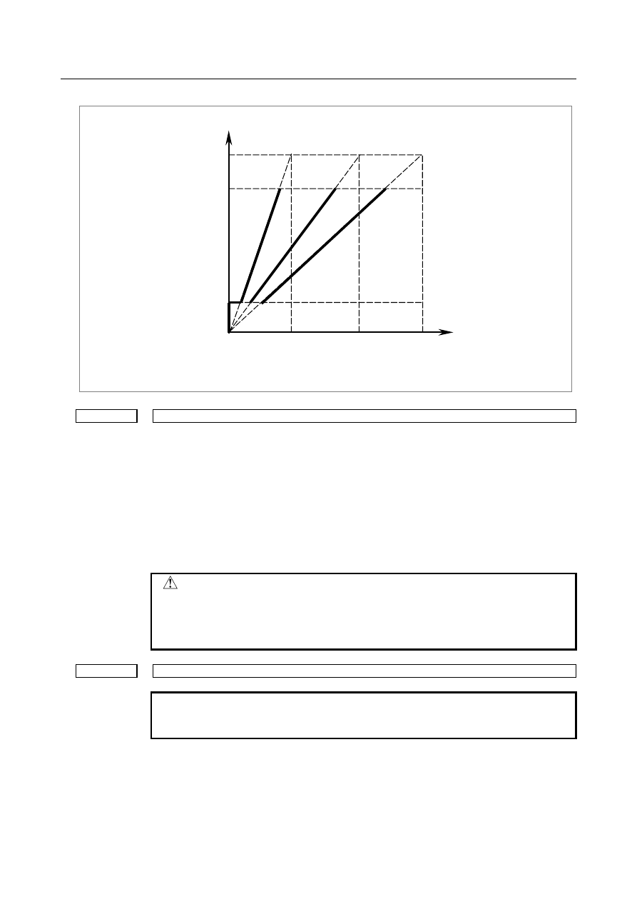
Set the maximum spindle speed corresponding to each gear.
B-64693EN-1/01
10. SPINDLE SPEED FUNCTION
- 1803 -
Spindle motor max. clamp speed
(Parameter No.3736)
Spindle speed command
(S command)
Max. speed (4095, 10V)
Spindle motor minimum clamp speed
(Parameter No.3735)
Spindle motor speed
Gear 1
Max. speed
(Parameter
No.3741)
Gear 2
Max. speed
(Parameter
No.3742)
Gear 3
Max. speed
(Parameter
No.3743)
3772
Maximum spindle speed
[Input type] Parameter input
[Data type] 2-word spindle
[Unit of data] min
-1
[Valid data range] 0 to 99999999
This parameter sets the maximum spindle speed.
When a command specifying a speed exceeding the maximum speed of the spindle is
specified , or the speed of the spindle exceeds the maximum speed because of the spindle
speed override function, the spindle speed is clamped at the maximum speed set in the
parameter.
CAUTION
1 When 0 is set in this parameter, the speed of the spindle is not
clamped.
2 When spindle speed command control is applied using the PMC,
this parameter has no effect, and the spindle speed is not clamped.
3775
Default P command value for spindle selection in multi-spindle control
NOTE
When this parameter is set, the power must be turned off before
operation is continued.
[Input type] Parameter input
[Data type] Word path
[Valid data range] 0 to 32767
When bit 3 (MPP) of parameter No. 3703 is set to 1 and bit 2 (MPA) of parameter No.
3706 is set to 1 in multi-spindle control, set a default P command value applicable if S_P_
is not specified even once after power-up.
10. SPINDLE SPEED FUNCTION
B-64693EN-1/01
- 1804 -
3781
P code for selecting the spindle in multi-spindle control
[Input type] Parameter input
[Data type] Word spindle
[Valid data range] 0 to 32767
If bit 3 (MPP) of parameter No. 3703 is set to 1, set the P code to select each spindle
under multi-spindle control. Specify the P code in a block containing the S command.
[Example] If the P code value for selecting the second spindle is set to 3,
S1000 P3;
causes the second spindle to rotate at S1000.
NOTE
1 This parameter is valid if bit 3 (MPP) of parameter No. 3703 is set
to 1.
2 If this parameter is set to 0, the corresponding spindle cannot be
selected by a P code.
3 Under multi-path control, the P code specified here is valid for each
path.
For instance, if the P code to select the first spindle of path 2 is set
to 21, specifying S1000 P21; in path 1 causes the first spindle of
path 2 to be rotated at S1000.
4 Identical P code values cannot be used for different spindles.
(Identical P code values cannot be used even if the paths are
different.)
5 When this parameter is used (when bit 3 (MPP) of parameter No.
3703 is set to 1), the spindle command selection signal is invalid.
6 To use this parameter, enable the multi-spindle control (bit 3 (MSP)
of parameter No,8133 is 1).
#7
#6
#5
#4
#3
#2
#1
#0
8003
FEX
[Input type] Parameter input
[Data type] Bit axis
NOTE
When this parameter bit is set, the power must be turned off before
operation is continued.
#3 FEX
The maximum feedrate that can be achieved by the machine during cutting feed or
continuous feed in PMC axis control, or spindle control with servo motor is:
0:
Not extended.
1:
Extended.
Restrictions
-
Parameters for setting the time constants for linear acceleration/deceleration after
interpolation and bell-shaped acceleration/deceleration after interpolation
When as the acceleration/deceleration type, linear acceleration/ deceleration after
interpolation or bell-shaped acceleration/ deceleration after interpolation is used for
each of rapid traverse, cutting feed, and manual feed, the maximum allowable time
constant is a half of the maximum value that can be set conventionally.
B-64693EN-1/01
10. SPINDLE SPEED FUNCTION
- 1805 -
The time constant parameters used are as follows:
Parameter No.
Meaning
1620
Time constant (T) used for linear acceleration/deceleration in rapid traverse
for each axis, or time constant (T1) used for bell-shaped
acceleration/deceleration in rapid traverse for each axis
1621
Time constant (T2) used for bell-shaped acceleration/deceleration in rapid
traverse for each axis
1622
Time constant for acceleration/deceleration in cutting feed for each axis
1624
Time constant for acceleration/deceleration in jog feed for each axis
1626
Time constant for acceleration/deceleration in threading cycles for each axis
1769
Time constant for acceleration/deceleration after cutting feed interpolation in
the mode of look-ahead acceleration/deceleration before interpolation
5271 to 5274
Time constant for acceleration/deceleration in rigid tapping extraction (first to
fourth gears)
5365 to 5368
Time constant for bell-shaped acceleration/deceleration in rigid tapping (first
to fourth gears)
-
The waveform display function of VCMD on the SERVO GUIDE or the SERVO
GUIDE Mate.
As the feedrate increases, more data is acquired for VCMD waveform display,
which can prevent waveforms from being displayed correctly.
CAUTION
When this function is enabled, the feedrate is extended to the
maximum value that can be specified for cutting feed or continuous
feed in PMC axis control if CMR is 1. If CMR is greater than 1, the
feedrate is limited to a value smaller than the maximum value that
can be specified.
Note that the maximum motor speed may be exceeded depending
on the feedrate specified.
#7
#6
#5
#4
#3
#2
#1
#0
11000
SRV
FSR
[Input type] Parameter input
[Data type] Bit axis
NOTE
When at least one of these parameters is set, the power must be
turned off before operation is continued.
#1 FSR
The axis to be subjected to servo motor-based spindle control is of a:
0:
Semi-closed system.
1:
Full-closed system.
#7 SRV
Spindle control with servo motor are:
0:
Not performed.
1:
Performed
NOTE
When spindle control with servo motor are used for an axis,
parameter No. 11010 must also be set for the axis.
10. SPINDLE SPEED FUNCTION
B-64693EN-1/01
- 1806 -
#7
#6
#5
#4
#3
#2
#1
#0
11001
TCR
[Input type] Parameter input
[Data type] Bit axis
#1 TCR
In SV speed control mode, time constant of acceleration/deceleration after interpolation
for spindle control with servo motor is:
0:
The parameter No. 1622.
(Time constant of acceleration/deceleration in cutting feed for each axis)
1:
The parameter No. 11016.
(Time constant of acceleration/deceleration in SV speed control mode for each axis)
Set this parameter for the axis to be placed under spindle control with servo motor.
11010
Spindle number used by spindle control with servo motor or spindle control with Cs contour control
NOTE
When this parameter is set, the power must be turned off before
operation is continued.
[Input type] Parameter input
[Data type] Byte axis
[Valid data range] 0 to maximum number of controlled spindles
This parameter sets a spindle number for a servo axis for which spindle control with servo
motor is performed.
NOTE
Set a spindle number for the axes set in bits 6 and 7 of parameter
No. 11000. For axes for which spindle control with servo motor is
not performed, set 0.
11011
Movement of spindle control with servo motor axis per revolution
NOTE
When this parameter is set, the power must be turned off before
operation is continued.
[Input type] Parameter input
[Data type] Real axis
[Unit of data] deg
[Min. unit of data] Depend on the increment system of the applied axis
[Valid data range] 0 or positive 9 digit of minimum unit of data (refer to the standard parameter setting table
(B))
(When the increment system is IS-B, 0.0 to +999999.999)
This parameter sets a movement of axis per revolution for which spindle control with
servo motor is performed.
11012
Spindle indexing speed for each axis
[Input type] Parameter input
[Data type] 2-word axis
[Unit of data] min
-1
[Valid data range] 0 to 99999999
B-64693EN-1/01
10. SPINDLE SPEED FUNCTION
- 1807 -
In spindle control with servo motor, set the spindle indexing speed for each axis.
If 0 is set, the spindle indexing speed is assumed to be the setting of parameter No. 11020
(speed (S
0
) for switching acceleration/ deceleration for each axis).
11013
Positioning deviation limit for each axis in movement
[Input type] Parameter input
[Data type] 2-word axis
[Unit of data] Detection unit
[Valid data range] 0 to 99999999
This parameter sets the limit of positional deviation for each axis during movement in
spindle control with servo motor.
11014
Positioning deviation limit for each axis in the stopped state
[Input type] Parameter input
[Data type] 2-word axis
[Unit of data] Detection unit
[Valid data range] 0 to 99999999
This parameter sets the limit of positional deviation at stop for each axis in spindle
control with servo motor.
11015
Maximum motor speed
[Input type] Parameter input
[Data type] 2-word axis
[Unit of data] min
-1
[Valid data range] 0 to 99999999
This parameter sets the maximum motor speed applicable when spindle control with
servo motor is performed.
11016
Time constant of acceleration/deceleration in SV speed control mode for each axis
[Input type] Parameter input
[Data type] Word axis
[Unit of data] msec
[Valid data range] 0 to 4000
In spindle control with servo motor, set the time constant of acceleration/deceleration
after interpolation in cutting feed for SV speed control mode. Set this parameter for the
target axis for spindle control with servo motor. Set the time constant used for
exponential
acceleration/deceleration
in
cutting feed,
bell-shaped
acceleration/deceleration after interpolation or linear acceleration/deceleration after
interpolation in cutting feed for each axis. Type of acceleration/deceleration is applied by
bits 0 (CTLx) and 1 (CTBx) of parameter No. 1610.
11017
FL rate of exponential acceleration/deceleration in SV speed control mode for each axis
[Input type] Parameter input
[Data type] Real axis
[Unit of data] mm/min, inch/min, deg/min (machine unit)
[Min. unit of data] Depend on the increment system of the applied axis
[Valid data range] Refer to the standard parameter setting table (C)
(When the increment system is IS-B, 0.0 to +999000.0)
In spindle control with servo motor, this parameter sets the lowest feedrate (FL rate) in
exponential acceleration/deceleration for velocity control.
10. SPINDLE SPEED FUNCTION
B-64693EN-1/01
- 1808 -
Set this parameter for the target axis for spindle control with servo motor.
11020
Acceleration/deceleration switching speed (S
0
) for each axis
[Input type] Parameter input
[Data type] 2-word axis
[Unit of data] min
-1
[Valid data range] 0 to 99999999
In spindle control with servo motor, this parameter sets the speed at which acceleration/
deceleration is changed to perform rotation control. (First step)
11021
Acceleration/deceleration switching speed (S
1
) for each axis
[Input type] Parameter input
[Data type] 2-word axis
[Unit of data] min
-1
[Valid data range] 0 to 99999999
In spindle control with servo motor, this parameter sets the speed at which acceleration/
deceleration is changed to perform rotation control. (Second step)
11030
Individual acceleration / deceleration 1 (Leg 1)
[Input type] Parameter input
[Data type] 2-word axis
[Unit of data] min
-1
/s
[Valid data range] 0 to 100000
In spindle control with servo motor, this parameter sets acceleration/deceleration to be
applied to perform rotation control. When the speed ranges from 0 to acceleration
switching speed 1, acceleration/deceleration 1 is applied. Acceleration switching speed 1
is the speed set in parameter No. 11020.
11031
Individual acceleration / deceleration 2 (Leg 2)
[Input type] Parameter input
[Data type] 2-word axis
[Unit of data] min
-1
/s
[Valid data range] 0 to 100000
In spindle control with servo motor, this parameter sets acceleration/deceleration to be
applied to perform rotation control. When the speed ranges from acceleration switching
speed 1 to acceleration switching speed 2, acceleration/ deceleration 2 is applied.
Acceleration switching speed 1 and acceleration switching speed 2 are the speeds set in
parameters Nos. 11020 and 11021, respectively.
11032
Individual acceleration / deceleration 3 (Leg 3)
[Input type] Parameter input
[Data type] 2-word axis
[Unit of data] min
-1
/s
[Valid data range] 0 to 100000
In spindle control with servo motor, this parameter sets acceleration/deceleration to be
applied to perform rotation control. When the speed ranges from acceleration switching
speed 2 to the maximum speed, acceleration/deceleration 3 is applied. Acceleration
switching speed 2 is the speed set in parameter No. 11021.
B-64693EN-1/01
10. SPINDLE SPEED FUNCTION
- 1809 -
10.20.2
Spindle Indexing Function
Format
G96.1 P_ R_ ;
After spindle indexing is completed, the operation of the next block is
started.
G96.2 P_ R_ ;
Before spindle indexing is completed, the operation of the next block
is started.
G96.3 P_ ;
After it is confirmed that spindle indexing is completed, the operation
of the next block is started.
P: Spindle selection with multi-spindle control
R: Stoppage angle [deg] (0 to (parameter No. 1260))
To specify address P, use parameter No. 3781 (P code for selecting a spindle in multi-spindle control).
To turn the position control mode ON without performing spindle indexing, do so after canceling the SV
speed control mode by issuing G96.1 command with no R specified when the motor is at a halt.
When the motor is rotating, issuing a G96.1 (or G96.2) command with no R specified results in the motor
coming to a halt by behaving in the same manner as for R0.
NOTE
1 When using G96.2, issue G96.3 before another spindle move command, to
make sure that the spindle is at a complete halt.
2 To issue G96.1, G96.2, or G96.3, use an independent block.
Spindle indexing command
-
Move command
(1) Command waiting for spindle indexing to be completed
If G96.1 is issued, the next block is executed after spindle indexing is completed.
(2) Command not waiting for spindle indexing to be completed
If G96.2 is issued, the next block can be executed before spindle indexing is completed.
-
Movement completion check command
G96.3 is used to check to see if spindle indexing is completed. If it has not been completed, the next
block waits for spindle indexing to be completed. If it is completed, the next block is executed.
-
SV speed control mode cancellation
If G96.1 is used to perform spindle indexing, the SV speed control mode is canceled when spindle
indexing is completed.
If G96.2 is used to perform spindle indexing, G96.3 can be used to check to see if spindle indexing is
completed and, if completed, cancel the SV speed control mode. Issuing G96.2 not followed by G96.3
cannot cancel the SV speed control mode even if spindle indexing is completed.
If SV speed control mode cancel, it is necessary to be commanded in the path to which the live tool axis
belongs.
-
Spindle indexing command during spindle rotation
Issuing G96.1 or G96.2 with a position specified during spindle rotation causes the spindle to stop at the
specified position.
Example)
M03 S1000 ; . . . . . . ... Rotation at S1000
G96.1 P1 R180.0 ; . . . . .. Stoppage of rotation at the 180
°
position
Нет комментариевНе стесняйтесь поделиться с нами вашим ценным мнением.
Текст